


Structural Loading Rules for Cleanroom Single Rails
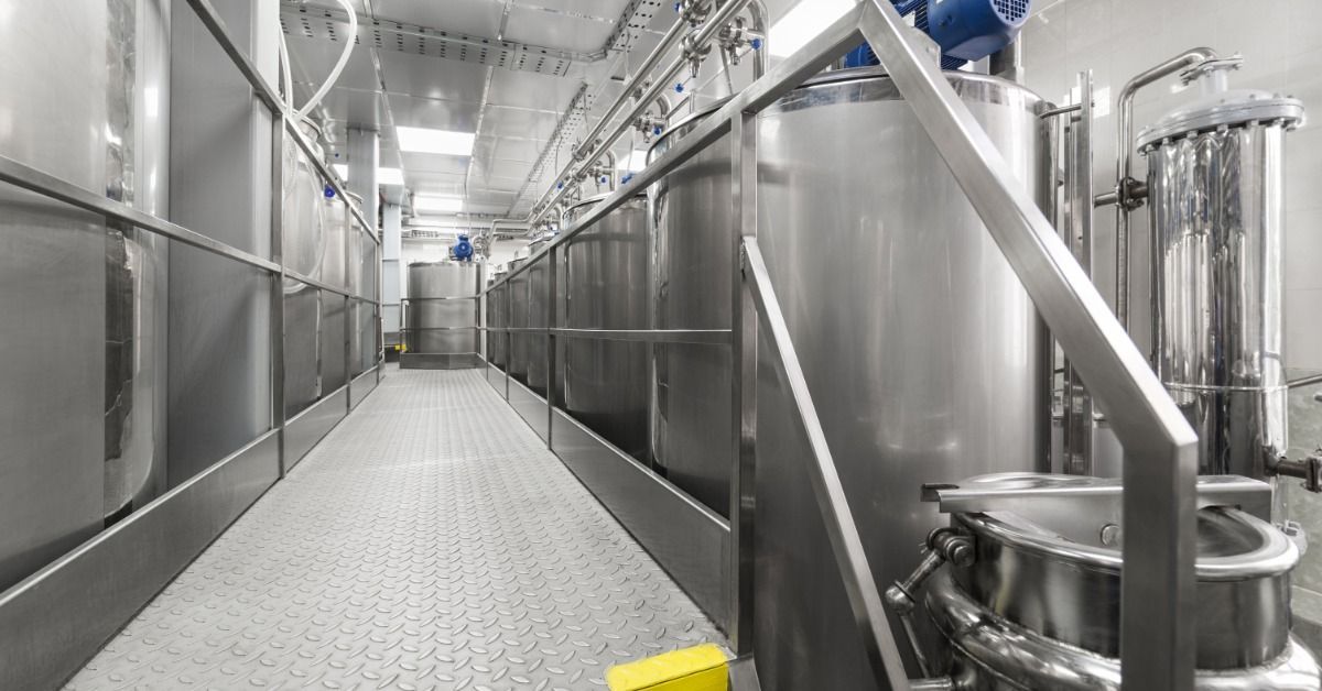
Cleanroom single rails may need to fit around equipment, wall systems, and other architectural features that leave limited room for posts and mounting points. Those restrictions affect more than the rail layout. The location of each support determines how forces move from the rail into the surrounding structure, while the capacity of that structure can limit where the system can safely attach.
These conditions make structural loading rules for cleanroom single rails an important part of planning the installation before fabrication. Project teams need to consider the required rail loads alongside support spacing, connection locations, and the capacity of the intended mounting points. Addressing those conditions early allows designers to adjust the configuration before the fabricator produces components for locations that cannot provide the necessary structural support.
Establish the Required Rail Loads First
Before determining rail dimensions or connection details, project teams need to establish the loads the system must resist. The 2024 International Building Code establishes loading requirements for handrails and guards, giving designers structural criteria to consider when developing the assembly. Applicable requirements can vary with project conditions, so the design team must identify the provisions governing the specific installation.
Starting with those requirements keeps later decisions tied to defined structural demands. Once the team establishes the design criteria, it can evaluate how forces will move through the assembly and determine which components require further attention.
Follow the Load Beyond the Top Rail
When someone applies force to the horizontal rail, the resulting load moves through the posts or brackets and their connections before reaching the supporting structure. Because each point along that path contributes to the system’s structural performance, designers need to evaluate how the components work together rather than assessing the rail independently.
Looking only at the visible member of a stainless steel handrail can overlook limitations elsewhere in the assembly. Even when the horizontal member can resist the required load, an inadequate connection or mounting point can limit the system’s performance. Evaluating the complete assembly allows project teams to identify those limitations where the rail transfers force between components.
Evaluate Shear at Connections
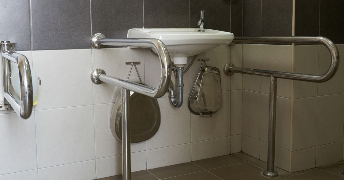
Lateral force places demand on the connections between rail components and their supports. As a post transfers force toward its mounting point, the connection must accommodate the resulting shear without separating structural evaluation from the conditions present at that location. Connection geometry therefore needs to reflect both the rail configuration and the intended mounting arrangement.
Cleanroom layouts can complicate those decisions when nearby equipment or architectural elements reduce the space available for connections. A detail that works in an open area may not fit within the clearances of the planned installation, while relocating it can change how the rail transfer's force. Addressing shear and connection geometry together allows designers to resolve those constraints before the fabricator develops finished components.
Determine Support Spacing Before Fabrication
The distance between posts or brackets affects how the rail carries force between its supports. Changing that spacing alters the relationship between the horizontal member and the points where loads enter the supporting structure, so designers cannot treat post locations as an architectural decision alone. Wider spacing may change the demands on the rail, while additional supports create more attachment locations that must fit the cleanroom layout.
Equipment clearances and access requirements can restrict those locations even further. Rather than positioning supports after the rail geometry has been established, project teams can coordinate spacing with the available mounting areas from the beginning. This approach reduces the chance that a structurally necessary support conflicts with equipment or lands where the surrounding construction cannot accommodate it.
Match Attachments to the Supporting Structure
A mounting surface may offer enough physical space for a post or bracket without providing the structural support that the rail requires. Cleanrooms can include lightweight walls, panels, curbs, or similar architectural elements, making it important to distinguish between the visible mounting surface and the structure that ultimately receives the force.
Increasing the size of a rail component does not resolve a limitation at the attachment point. For example, changing the post can alter that component without improving the structure beneath its base. Designers instead need to establish where the load can enter appropriate supporting construction, then develop the mounting arrangement around that condition. Doing so keeps additional material from becoming a substitute for a complete load path.
Work Within Architectural Weight Limits
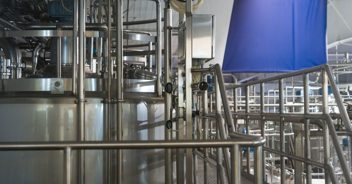
Structural capacity and architectural constraints can create competing priorities. Cleanroom projects may limit the size or weight of rail components because of available space, surrounding construction, or other design requirements, yet reducing the assembly cannot come at the expense of the structural criteria established for the installation.
These constraints make targeted design decisions more useful than simply increasing component size. Project teams can examine where the assembly carries its highest demands and determine how the rail configuration interacts with its supports. When a limitation comes from the surrounding architecture, changing the rail alone may not address it. Coordinating the two allows the finished system to respond to structural requirements without adding bulk where it provides no practical benefit.
Define Fabrication Requirements Before Production
Once the project team resolves structural and architectural constraints, those decisions can guide the fabrication. Before production begins, the fabricator should have established project information covering:
- Required rail dimensions
- Post and support locations
- Mounting interfaces
- Applicable structural criteria
- Installation clearances
Clear fabrication requirements separate design decisions from production work. The fabricator can build around established criteria without independently determining conditions that belong to the project design. When project-specific information reaches fabrication early, the finished assembly has a clearer relationship to the supports and spatial restrictions identified for the installation.
Plan the Complete Load Path for Cleanroom Rails
Structural loading rules for cleanroom single rails extend beyond selecting a horizontal member capable of carrying an applied force. That force needs a continuous path through the rail assembly and into suitable supporting construction, which makes connections and support locations part of the same structural discussion. Cleanroom layouts can complicate that path when equipment restricts mounting areas or architectural limitations reduce the available design space.
CMPI fabricates custom single-line stainless steel rail systems for commercial and industrial applications. For cleanroom projects with established structural, mounting, and architectural requirements, contact CMPI to discuss how the team can incorporate those specifications into the fabricated rail system.
Source
International Code Council (ICC. 2026. “Digital Codes.” Iccsafe.Org. https://codes.iccsafe.org/s/IBC2024V2.0/chapter-16-structural-design/IBC2024V2.0-Ch16-Sec1607.9.1.1.